The SISfm Map Compiler is an administrator utility which translates site and building plans from SIS SWD (SIS Workspace Definition) files into Facility maps as SVG and XML files for use by the SISfm Map Enquiry module.
Map Compiler is available:
Map Compiler reads SIS files at the following physical locations:
DataFolderSis\site_code\site.SWD
and:
DataFolderSis\site_code\floor_loc_code.SWD
where:
DataFolderSis is the value of that setting for this application (see below) site_code is the site code defined by the SiteId and SiteCode settings for this application floor_loc_code is the building floor location code
Instead of SWD files at these locations, Windows shortcut files with the same names can be used to refer to SWD files at other locations.
Use Compile DWG Floor Plans to translate building floor plan DWG files, specified by the field to the left, into corresponding SVG and XML files. See Compiling DWG Floor Plans below. The field must be as for Compile Floor Plans.
Use Compile Floor Plans to translate building floor plan SWD files, specified by the field to the left, into corresponding SVG and XML files. The field value must be a valid building floor location code, or a partial one to select all that start with that value (for legacy reasons, any asterisk (*) characters are removed from the value first).
Use Compile Site Plan to translate an SWD file for a site, selected from the dropdown selector to the left, into corresponding SVG and XML files.
Use Update Areas to update room areas (rm.area) and gross floor areas (fl.area_gross_int and fl.area_gross_ext) in the database, specified by the field to the left as for Compile Floor Plans.
Use Help in the desktop edition to view this documentation.
The desktop edition of Map Compiler can also be run non-interactively (e.g. as a Windows scheduled task) by including the following command line parameters. These are all optional and may be specified in any order. Parameter names and qualifiers are not case-sensitive, parameter values must be enclosed in double quotes if they contain spaces, names and values must be separated by one or more spaces.
/BATCH Run Map Compiler non-interactively. By default no data is compiled. /LOGFILE filename Write the log to the specified file. If omitted, or if the specified file is invalid, the log is written to the console. /APPEND Append entries to the log file if it already exists. If omitted the contents of an existing log file are replaced. /DWGDATA [code[,code...]] Compile map data from DWG files, optionally restricted by one or more comma-separated codes. Each code may be a Compile Floor Plans field value. /MAPDATA [code[,code...]] Compile map data from SWD files, optionally restricted by one or more comma-separated codes. Each code may be either a site_id value or a Compile Floor Plans field value. /UPDATEAREAS [code[,code...]] Update room and gross floor areas, optionally restricted by one or more comma-separated codes. Each code may be a Compile Floor Plans field value. /SINCE [SWD|DATASET] [date/time] Restrict map data compilation to files modified since a specified date/time if supplied, otherwise to the date/time that Map Compiler was last run on the same computer. The qualifier SWD or DATASET may be used to further restrict /MAPDATA compilation to only internal overlays, or to only external file overlays.
The web edition of Map Compiler uses GeognoSIS stored procedures supplied in the SISfm Administrator installation as Map Compiler\GeognoSIS\SP_SISfm.dll, which must be copied to the GeognoSIS StoredProcedures\DotNet folder.
The web edition of Map Compiler reads its settings from the SISfm web configuration (see the Map Compiler section of Configuration Settings, and requires setting MapCompilerGeognoSIS.
The desktop edition of Map Compiler reads its settings from the file MapCompiler.exe.config in the same folder as MapCompiler.exe. Use a plain text editor such as Notepad to change settings to suit your environment.
Most Map Compiler settings should be the same for both editions, and should therefore be in a shared configuration file (see Configuration Administration) as shown in the example below.
File folder settings must be specified separately as URLs in the non-shared web configuration, and as physical paths in MapCompiler.exe.config.
The desktop edition requires the following settings in MapCompiler.exe.config:
| Key | Value | |
| CadcorpLicenceServer | The name or IP address of the SIS licence server, or no-net to specify a local licence. Optional, if omitted a local licence will be used if present, otherwise the server specified in Windows environment variable CADCORP_LICENCE_SERVER_LIST, otherwise a server obtained by network broadcast. (Cadcorp was the original owner of SIS). | |
| CadcorpLicenceLevel | The level of the SIS licence to use, either Modeller or Manager. Optional, if omitted a Modeller licence will be used if available, otherwise a Manager licence. | |
| MapDatasetFolder | The physical path of a folder under which all map dataset files are stored, corresponding to the URL defined by the web application MapDatasetFolder setting. Optional, if both are not defined the Map Enquiry Layer download button is not displayed. |
Map Compiler also reads the following settings which should normally be shared with the SISfm web application:
DbConnectionIFM
DbConnectionAFM

FacilityType

LocCodeFormat
LocCodeOutput
LocCodeOutputB

EmView
EmNameFields
EmNumberField
EmExtraKeyField

BlAreaField

SiteId
SiteCode

MapTheme
MapLegend

MapLayerAlias

MapLayerPoint
MapLayerLink
MapLayerNetwork
MapLayerTopo
Following are typical configuration files, with Map Compiler settings for the test data supplied with the SISfm web application at its default web site location:
<?xml version="1.0"?>
<configuration>
  <appSettings file="C:\inetpub\wwwroot\SISfm\shared.config">

    <add key="CadcorpLicenceServer"    value="" />
    <add key="CadcorpLicenceLevel"     value="Modeller" />

    <add key="DataFolderSis"           value="C:\inetpub\wwwroot\SISfm\test\sisdata\" />
    <add key="DataFolderMap"           value="C:\inetpub\wwwroot\SISfm\test\mapdata\" />
    <add key="DataFolderMapIcon"       value="C:\inetpub\wwwroot\SISfm\test\mapicons\" />

    <add key="MapDatasetFolder"        value="" />

    <add key="UploadWebsite"           value="" />
    <add key="UploadAuthTokenUrl"      value="" />
    <add key="UploadAuthClientId"      value="" />
    <add key="UploadAuthClientSecret"  value="" />
  </appSettings>
</configuration>
<?xml version="1.0"?>
<appSettings>
  <add key="AppConfigFile" value="shared.config" />

  <add key="DataFolderSis"             value="~/test/sisdata/" />
  <add key="DataFolderMap"             value="~/test/mapdata/" />
  <add key="DataFolderMapIcon"         value="~/test/mapicons/" />

  <add key="MapDatasetFolder"          value="" />

  <add key="MapCompilerGeognoSIS"      value="http://localhost:4601/GeognoSIS/GeognoSIS.wsdl" />
</appSettings>
<?xml version="1.0"?>
<appSettings>
  <add key="NolFile1"                  value="C:\inetpub\wwwroot\SISfm\test\sisdata\test.nol" />

  <add key="DwgTemplateSwd"            value="C:\inetpub\wwwroot\SISfm\test\sisdata\DwgTemplate.swd" />
  <add key="DwgDataFolder"             value="C:\inetpub\wwwroot\SISfm\test\dwgdata\" />
  <add key="DwgDataFolderAfm"          value="C:\inetpub\wwwroot\SISfm\test\dwg_afm\" />
  <add key="DwgDataFolderAfmFlat"      value="FALSE" />
  <add key="DwgDataFolderForOverlay1"  value="" />
  <add key="DwgInsertParams"           value="" />
  <add key="DwgGrossAreaType"          value="BOTH" />
  <add key="DwgGrossAreaLayer"         value="Gross Areas" />
  <add key="DwgRoomAreaLayer"          value="Space" />
  <add key="DwgRoomNumberLayer"        value="Room Numbers" />
  <add key="DwgSaveSwd"                value="FALSE" />

  <add key="OverlayExclude"            value="route-vehicle,route-pedestrian" />
  <add key="OverlayLinks"              value="buildings,carparks,otherlinks,space" />

  <add key="ExplodeShapes"             value="TRUE" />

  <add key="ExportSVG"                 value="TRUE" />
  <add key="ExportSVGZ"                value="FALSE" />
  <add key="ExportPDF"                 value="TRUE" />
  <add key="ExportCentroids"           value="TRUE" />

  <add key="PDFPrintTemplate"          value="IFM A3 Landscape PDF" />
  <add key="PDFPaperFormat"            value="A3*@600" />

  <add key="PDFParameters"             value="" />

  <add key="ViewRotationAttribute"     value="" />

  <add key="BuildingName"              value="" />

  <add key="LinkColours"               value="" />

  <add key="LinkAttribute"             value="" />
  <add key="DescAttribute"             value="" />
  <add key="LocCodeAttribute"          value="" />

  <add key="MapFloorLayerPointParams1" value="Room Zones|db=2+tables=RoomZones,RoomZones,RoomZones,RoomZones,RoomZones,RoomZones,RoomZones,RoomZones+columns=map_name,x,y,scale,angle,icon,link,description+where=map_name='$$map_name$$'+nFieldX=1+nFieldY=2" />
  <add key="MapFloorLayerPointParams2" value="HAZMAT|db=2+tables=hazmat,hazmat,hazmat,hazmat,hazmat+columns=hazmat_id,x,y,name,notes+where=site_id='$$site_id$$' AND bl_id='$$bl_id$$' AND fl_id='$$fl_id$$'+nFieldX=1+nFieldY=2" />
</appSettings>
Map Compiler obtains two extents from the SWD for use by Map Enquiry:
The view rotation is ignored for a site plan SWD but is compiled as the Map Enquiry building alignment for a floor plan SWD so that floors can be viewed orthogonally, when it must be the same for all floors of a building. The view rotation is as defined by the SIS View / Map Views / Rotate command unless setting ViewRotationAttribute is set.
Overlays can be renamed or excluded by using MapLayerAlias settings. In the resulting names, the dot (".") character is interpreted as a folder path separator. Note that overlay names should not be the same as folder names (i.e. if there is an overlay named A.B.C there should not be overlays named A.B or A.
The last separator in a folder path may instead be a double dot ("..") to signify that such overlays are alternatives: their selection will use radio (option) buttons instead of checkbox buttons (or equivalent button styles).
Compiling DWG floor flans requires the Map Compiler settings commencing with Dwg.
Use Compile DWG Floor Plans to compile floor plans from DWG files to SISfm (without requiring SWD files). The following options are available:
Archibus DWG files include xData for linking elements such as room numbers and polylines to Archibus, and from this xData SISfm room location codes are derived.
Options 1 and 2 create an intermediate Archibus DWG file in DXF format (at a temporary location for option 1). DXF format is used because SIS cannot export MTEXT entities, so these are created by editing the exported DXF. Furthermore, SIS does not provide access to the DWG entity handles, so these do not match those in the xData. Therefore option 2 currently does not work, and option 3 requires Archibus DWG files prepared using the Archibus Smart Client.
Note that Map Compiler does not publish Archibus enterprise graphics. This must be done using the Archibus DWG Editor (or AutoCAD with the corresponding Archibus plug-in).
For options 1 and 2, DWG files are processed as follows.
For options 1 and 2 (continued) and for option 3, the SWD file specified by setting DwgTemplateSwd is loaded and:
Note that the SWD file specified by setting DwgTemplateSwd should contain File overlays referencing a representative DWG or DXF file (e.g. located alongside it) with Expression layer filters such as _layer$ In ("RM$") and Not _layer$ In ("EQ$","RM$").
The following messages may be issued in a dialog box, or to the log in batch mode:
Setting MapCompilerGeognoSIS is not defined
The MapCompilerGeognoSIS setting must be defined to use the web edition.
No SIS ActiveX Manager or Modeller licence is available
Check that SIS is installed, including one of these licences, to use the desktop edition.
Unable to access page (message)
Check that the UploadWebsite settiing is correctly defined.
SIS library not found: filename
Check that filename exists, or adjust NolFile configuration settings.
The following messages may be issued to the console in batch mode:
Error creating specified log file filename
File name not specified
No value was supplied for the /LOGFILE parameter.
Error creating specified log file filename
message
The value supplied for the /LOGFILE parameter is invalid.
The following messages may be issued to the log:
MapCompiler parameters
Confirms the supplied command line parameters for batch compilation.
Invalid command line arguments: arguments
Command line arguments are not those required for batch compilation.
Invalid date/time value: value
Invalid /SINCE date value for batch compilation.
Invalid last run date/time value: value
The LastRun value in the key HKEY_CURRENT_USER\Software\VB and VBA Program Settings\IFM\SISfm Map Compiler is not a date (if value is (undefined), use /SINCE with a date value, otherwise remove this value from the registry).
Compiling plan [ SWDs | DATASETs ] updated since [ last run at ] date
Confirms /SINCE action for batch compilation.
Select plan to compile
The initial log panel message, or no plan was specified.
No plans found
You have tried to compile an item or range of items which do not exist in the database.
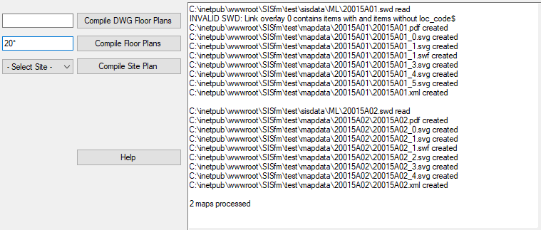
filename.swd read
filename.dwg read
Advice that a plan compilation is starting.
ERROR: Topology overlay name name is invalid
ERROR: Topology overlays have different datasets: name1, name2,...
ERROR: Topology "topoRoot" tables invalid - valid SQL for schema and DDL is: SQL
ERROR: Topology overlay "name" item with attNamePoint="idPoint" and attNameLine="idLine" is not reached by that line
ERROR: Topology requires two overlays name.* - one filtering pointClass items, the other lineClass items
ERROR: Topology table "table" name is invalid
ERROR: Topology overlay name has duplicate itemClass items, IDs id1,id2,...
ERROR: Topology overlay name has Link items with more than two vertices, id1,id2,...
ERROR: Topology overlay name has Link items with line not straight, id1,id2,...
ERROR: Topology overlay name items do not all have attribute idAtt
ERROR: Topology overlay name items with idAtt="id" do not form a single directed network, unconnected node IDs id1,id2,...
ERROR: Topology "topoRoot" table "table" would require more than one field "field" due to an item property/attribute name clash
ERROR: Topology "topoRoot" table "table" does not exist
ERROR: Topology "topoRoot" table "table" requires field field
ERROR: Topology overlay "name" must have Editable status to update its item attribute "att" value(s)
Refer to Topological overlays above.
filename.dwg added as overlay name
A DWG file overlay has been added when compiling a DWG file.
ERROR: Compiling DWG files with DwgDataFolder defined is not supported with UploadWebsite set
Check the DwgDataFolder and UploadWebsite settings.
ERROR: DWG dataset invalid: filename.dwg
DWG compilation was unable to read this DWG file.
ERROR: no dwgname value is defined for rooms on floor loc_code
ERROR: different dwgname values are defined for rooms on floor loc_code
DWG compilation obtains the names of Archibus DWG files from the rm.dwgname field for rooms on that floor, or from fl.dwgname if the floor has no rooms.
ERROR: DWG layer setting cannot be renamed to layer because it already exists
DWG compilation found that the layer GROS$, RM$ or A-ROOM-NO already exists, when setting DwgGrossAreaLayer, DwgRoomAreaLayer or DwgRoomNumberLayer is used.
WARNING: DWG layer RM$ contains count1 Polygon items, layer A-ROOM-NO contains count2 BoxText items
DWG compilation found a mismatch between the number of room polygons and their numbers.
ERROR: DWG layer RM$TXT already exists
DWG compilation found that the layer it creates for Archibus room numbers already exists.
ERROR: DWG layer GROS$ contains count Polygon items
DWG compilation found that the gross area layer does not contain either 1 or 2 polygons.
WARNING: DWG layer GROS$TXT already exists - renamed to GROS$TXT_OLD
DWG compilation found that the layer it creates for Archibus gross area labels already exists.
WARNING: DWG layer RM$ area [ at extents ] contains count room numbers [ list ]
DWG compilation found a room polygon which does not contain 1 room number. When no room number is found, extents are provided for locating the room, otherwise a room number list.
WARNING: DWG layer RM$TXT values not in rm.rm_id: list
DWG compilation found room numbers in the DWG which do not match any value of field rm.rm_id for this floor.
WARNING: Compiling DWG files with DwgViewRotationField defined is not supported with UploadWebsite set
Check the DwgViewRotationField and UploadWebsite settings.
WARNING: rm.rm_id values not in DWG layer RM$TXT: list
DWG compilation found values of field rm.rm_id for this floor which do not match any room number in the DWG.
WARNING: Unable to get room ID from DWG xData for count rooms
DWG compilation found invalid xData values.
INVALID SWD: Link overlay index contains items other than Point, Node, LineString, Link, Polygon, MultiPoint, MultiLineString, MultiPolygon
The SWD is compiled but unexpected results may occur.
INVALID SWD: Link overlay index contains count items with attribute='value'
INVALID SWD: Link overlay index contains items with attribute values not in the database: 'value,...'
INVALID SWD: Link overlay index does not contain building 'value' that is in the database
INVALID SWD: Link overlay index does not contain rooms with attribute values that are in the database: 'value,...'
The SWD is compiled but unexpected results may occur. On a site or floor plan, a BuildingLocCodeAttribute or LocCodeAttribute value does not specify a building or room that exists in the database, or vice versa.
INVALID SWD: Link overlay index contains more than one item for building 'value'
The SWD is compiled but unexpected results may occur.
INVALID SWD: Link overlay index contains items with no description, which is required for point layers
The SWD is compiled but unexpected results may occur. A MapLayerPoint setting specifies that the overlay is to be compiled as a point layer for. The overlay DescAttributeFormula$ attribute and the DescAttribute setting are used to determine item descriptions.
ERROR: Unable to copy filename to filename (message)
Check filing system permissions.
ERROR: Unable to export to filename (message)
Check filing system permissions.
ERROR: cannot export width x height PNG: filename
Check filing system permissions. Check ExportFloor PNG scale.
ERROR: file does not exist: filepath
You have tried to compile an item which exists in the database, but its SIS SWD file or Archibus DWG file is not present.
ERROR: file filename does not exist under folderpath
You have tried to compile an item which exists in the database, but a search for its Archibus DWG file has not found it.
ERROR: n files filename exist under folderpath
You have tried to compile an item which exists in the database, but a search for its Archibus DWG file has found more than one.
ERROR reading item (WriteLayerXml): message
An unexpected error occurred, consult IFM for assistance.
WARNING: Manager licence in use, and Insert items found - not exploded or simplified
A SIS ActiveX Modeller licence is required to process Insert items correctly.
WARNING: Manager licence in use, and Point items found - symbols not exploded
A SIS ActiveX Modeller licence is required to process Point items correctly.
filename created
Advice that PDF, DWG, SWD, SVG, XML and image files have been created or replaced.
Overlay building_floors..N added
Advice that for a site plan an overlay has been added for building_floors level N.
Uploading to upload_website
Advice that file uploading is commencing.
filename uploaded
Advice that a file has been uploaded.
n plan[s] generated
n file[s] generated
Summary of the plans and files generated.
Compiling building data is not supported with UploadWebsite set
Check the UploadWebsite setting.
filename created, n buildings
Summary of the building data generated while compiling a site plan.
Compiling floor data is not supported with UploadWebsite set
Check the UploadWebsite setting.